
DRAWING-BASED INDUSTRIAL BEARING PARTS
Babbitt Bearing Manufacturing Process
A drawing-defined process connects backing preparation, lining formation and final geometry. The route and inspection points are agreed for the part being manufactured.
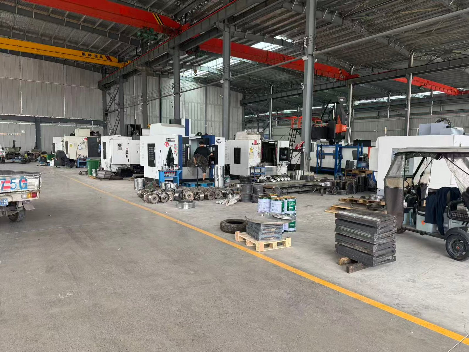
The manufacturing sequence
- Backing preparation. Inspect the shell or pad, prepare the specified geometry and remove contamination, oxidation and damaged material.
- Tinning. Apply the intermediate bonding layer using a procedure appropriate to the backing and lining alloy.
- Centrifugal casting. Secure the part in suitable tooling and control pouring, rotation and cooling for the specified lining. The casting route depends on part geometry; static casting may be reviewed where appropriate.
- Bond inspection. Check the lining-to-backing bond at the planned stage, using the agreed method, coverage and acceptance criteria.
- Machining. Finish the bore, outside fit, faces, oil passages and locating features to the approved drawing.
- Scraping, where specified. Finish the contact areas and oil-entry features according to the drawing and assembly requirements.
- Final inspection. Verify specified dimensions, lining condition, finish, marking and the required records before release.
Process details belong to the part specification
Alloy grade, backing condition, lining thickness, casting route and finished clearances are reviewed together. A generic process description is not a temperature, speed or performance guarantee.
For replacement parts, retain the approved drawing revision and identify any requested material or geometry change.
Refurbishment requires an initial assessment
For an existing bearing, the backing condition and repair scope are checked before a re-lining route is confirmed. Send photos, the original drawing, operating history and details of the failed area.