
DRAWING-BASED INDUSTRIAL BEARING PARTS
Hydro Turbine Bearings
This family presents bearing components for hydro turbine equipment, including cylindrical, flanged and segmented configurations. Use the images to identify an arrangement and send the equipment drawing or sample information for review. For segmented parts, include the number, outline and mounting details of the required elements. The material, lubrication arrangement, mating dimensions and inspection requirements are established for the specified assembly before manufacture.
ON THIS PAGE
Illustrated Configurations
9 configurations in this family. Catalogue references identify illustrated configurations; they are not standard model numbers.
Images illustrate product configurations. Final dimensions, materials and acceptance requirements are confirmed in the agreed specification.
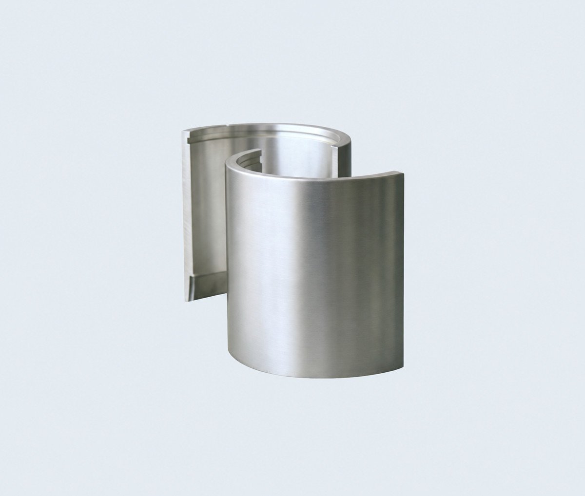
P011
Hydro Turbine Bearing
A bearing component for hydro turbine equipment.
Two cylindrical half shells shown together as a matching pair.
P026
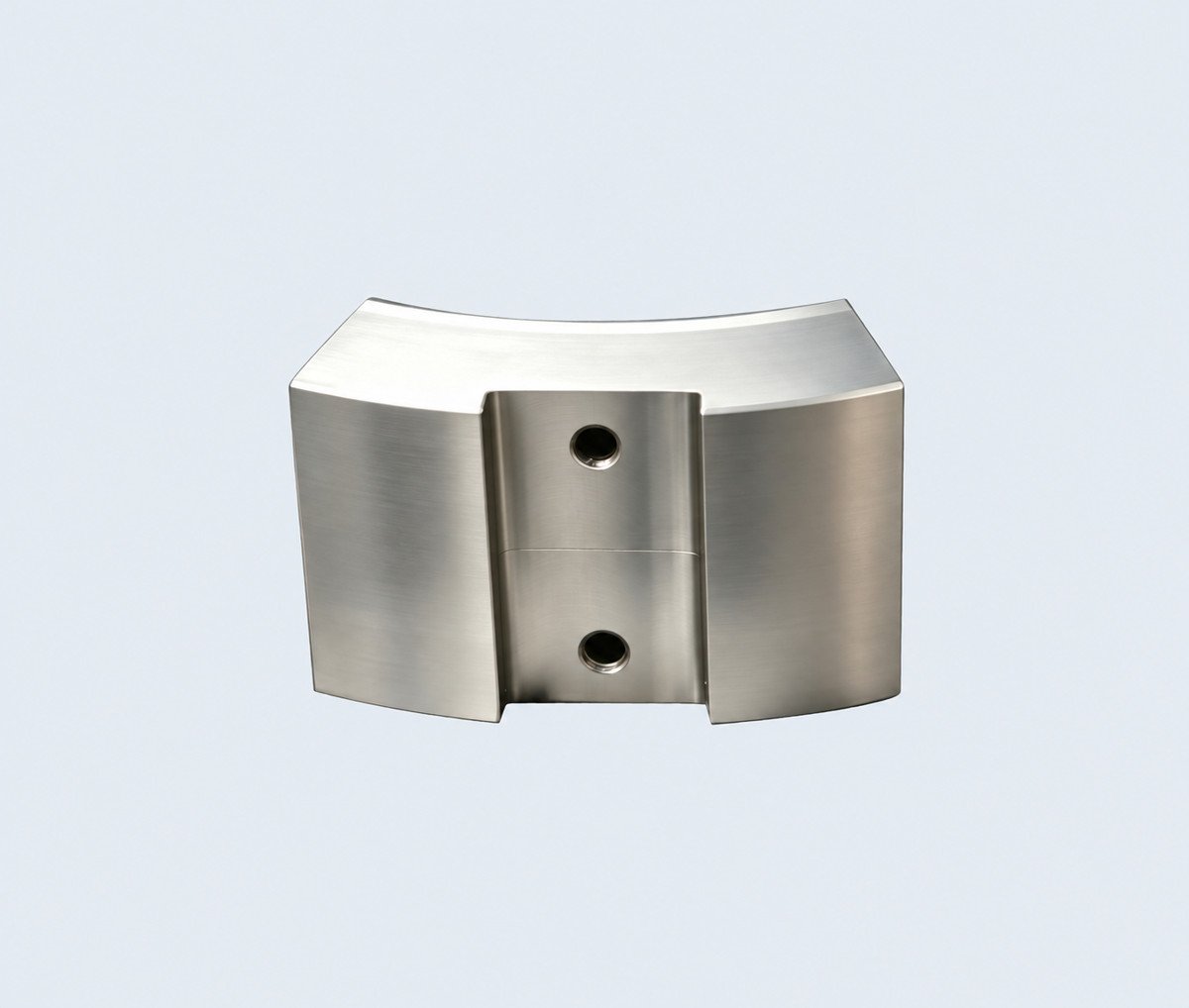
Hydro Turbine Bearing
A bearing component for hydro turbine equipment.
Curved split component with two visible openings on the outer face.
P028
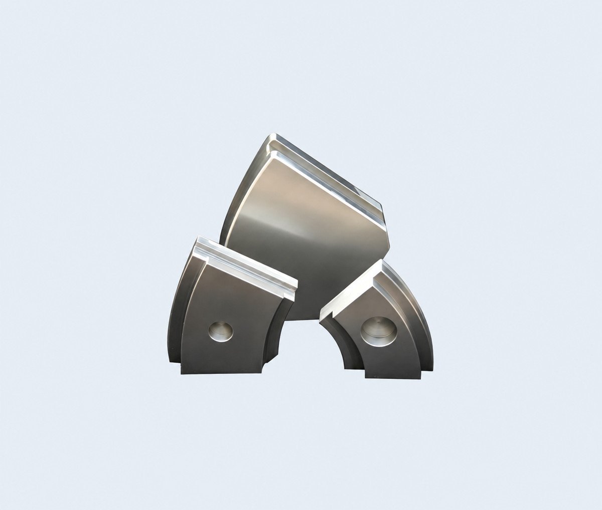
Hydro Turbine Bearing
A bearing component for hydro turbine equipment.
Three curved bearing segments shown together.
P036
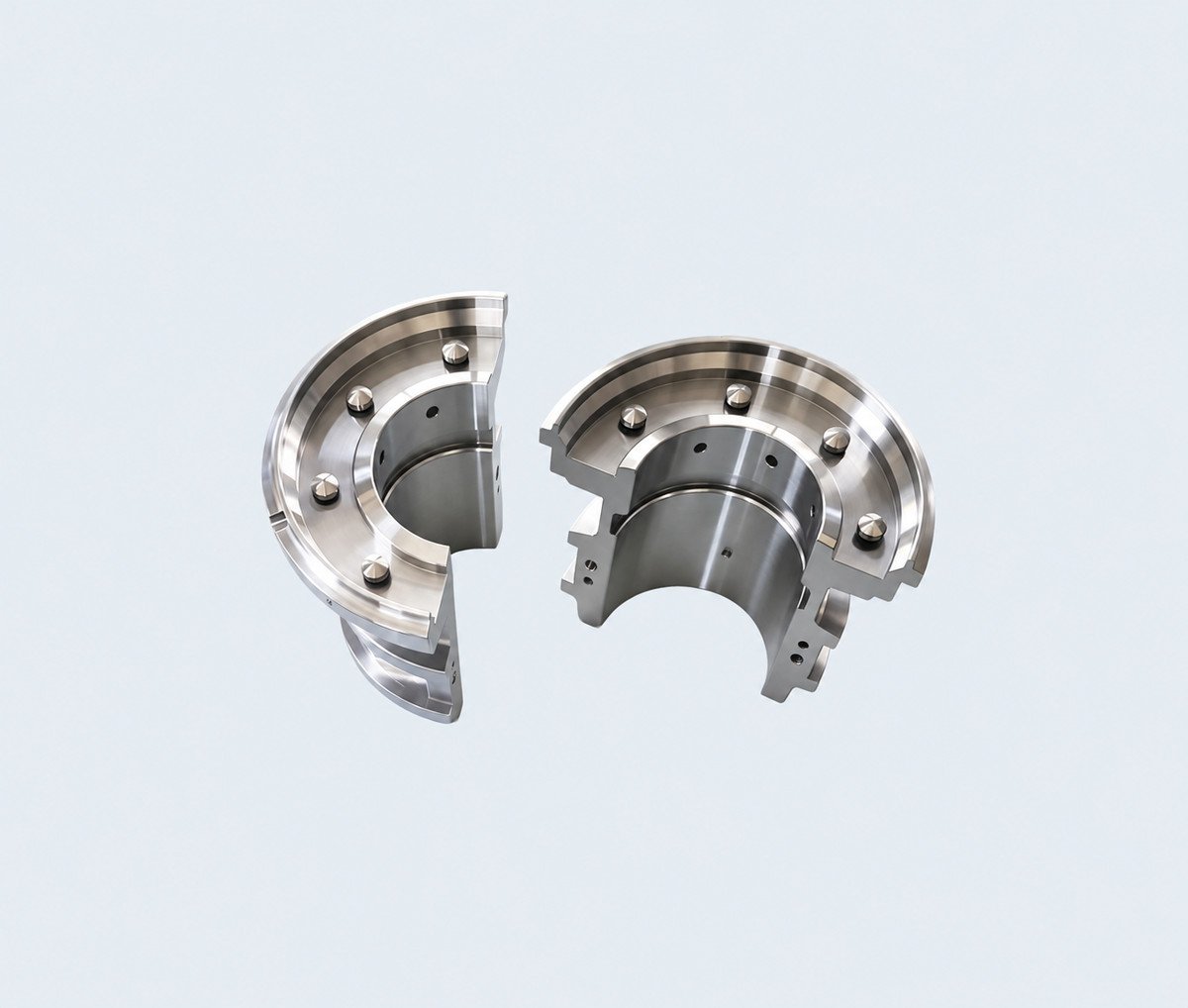
Hydro Turbine Bearing
A bearing component for hydro turbine equipment.
Matching split bearing components with flanged outer faces.
P090
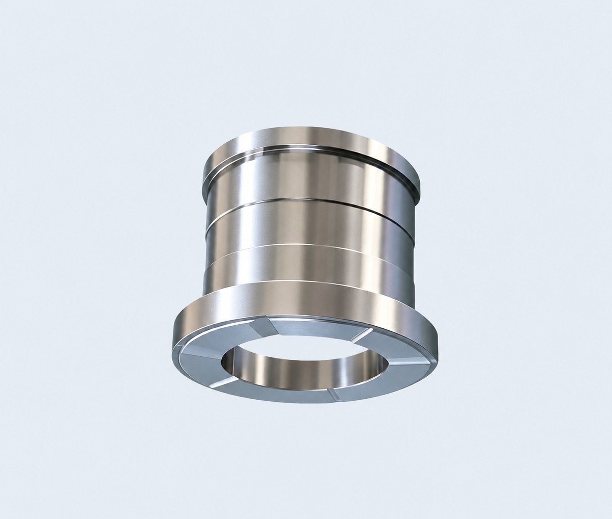
Hydro Turbine Bearing
A bearing component for hydro turbine equipment.
Cylindrical bearing configuration with several machined outer steps.
P091
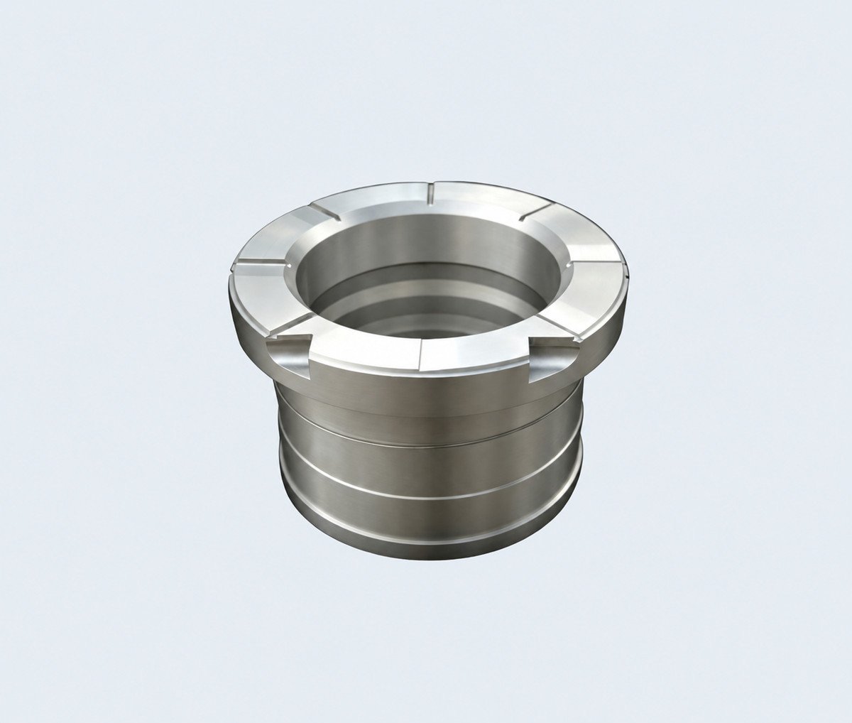
Hydro Turbine Bearing
A bearing component for hydro turbine equipment.
Flanged cylindrical configuration with a recessed central opening.
P092
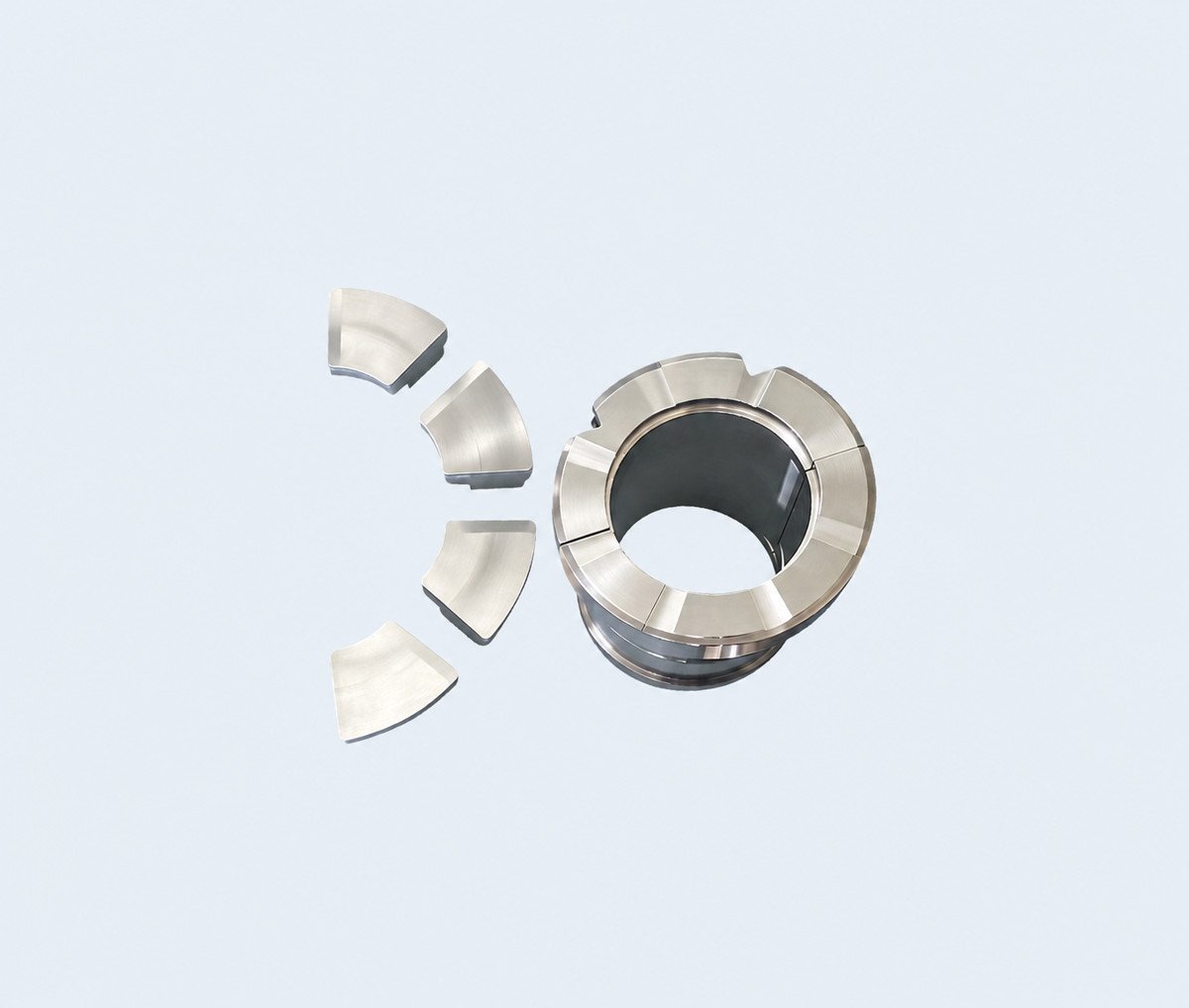
Hydro Turbine Bearing
A bearing component for hydro turbine equipment.
Bearing assembly shown with separate curved bearing segments.
P093
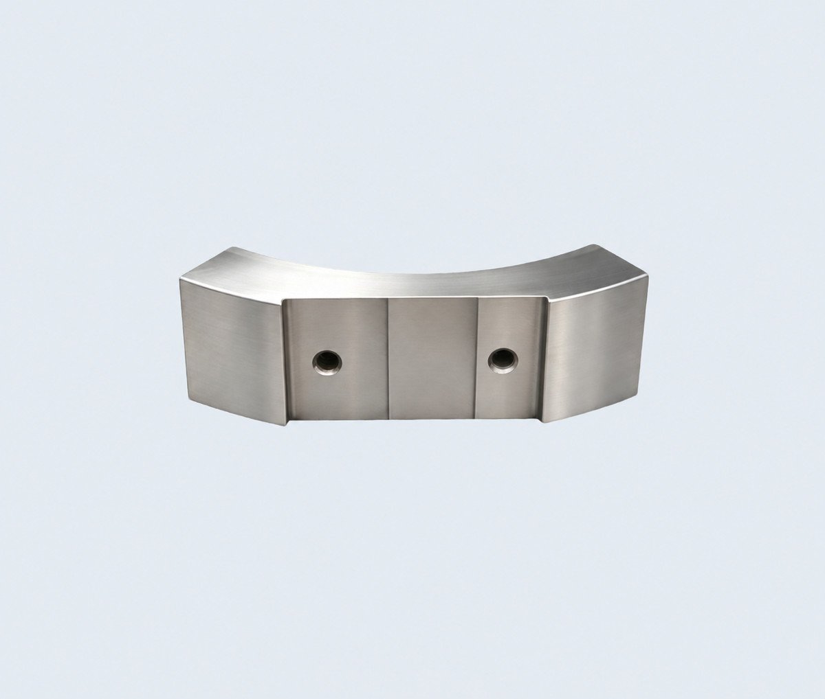
Hydro Turbine Bearing
A bearing component for hydro turbine equipment.
Single curved bearing component with two visible outer openings.
P094
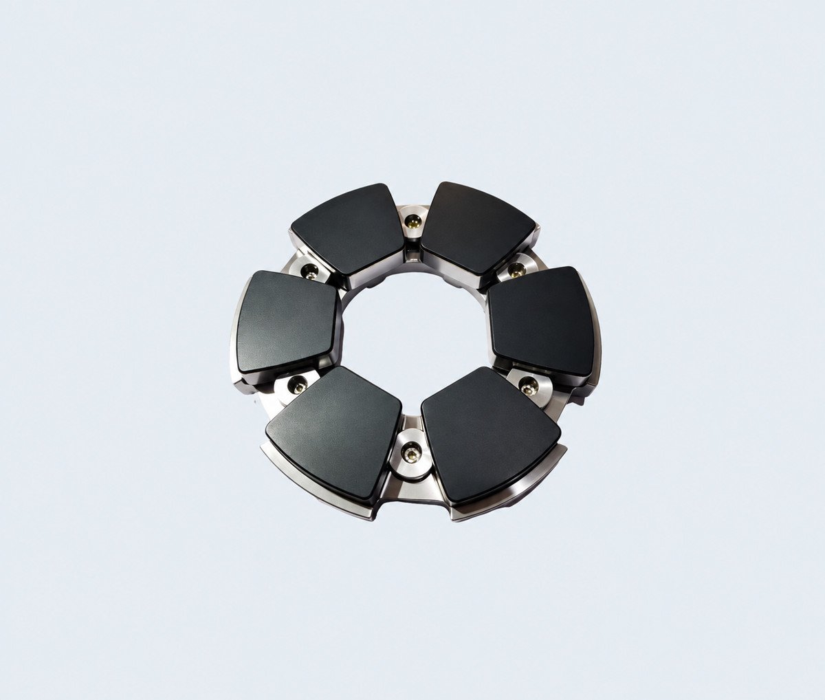
Hydro Turbine Bearing
A bearing component for hydro turbine equipment.
Circular arrangement of individual dark bearing pads.
Customisation for Your Drawing
Start with a drawing, a sample or specified dimensions. Define the material, lubrication features, mounting details and finished fit required by your equipment.
- Cylindrical or segmented geometry, including pad outline and arrangement.
- Bore, flange, mounting and mating dimensions.
- Specified bearing materials and lubrication features.
- Finished fit, surface requirements and order-specific documentation.
Inspection and Quality Documents
Agree critical dimensions, material requirements, inspection coverage, acceptance criteria and required documents during order review. Inspection methods and records are scoped to the part and the requested construction.
- Agree which component and assembly dimensions are critical to acceptance.
- Specify material records and applicable surface or lining checks.
- Confirm the inspection criteria for mating and mounting features.
- Define identification, reporting scope and any required customer review points.
Information for a Quote
Include the catalogue reference, quantity, delivery destination and available drawings. Add the equipment model, bearing position, operating conditions and any project-specific inspection requirements where known.
- Drawing revision, units and the required configuration.
- Material specification, critical tolerances and lubrication features.
- Equipment model, bearing position and operating conditions where known.
- Quantity, delivery destination and requested inspection records.
For a worn sample, identify any dimensions that need to be restored.
Discuss your custom bearing requirement
Include the catalogue reference, quantity, delivery destination and available drawings. Add the equipment model, bearing position, operating conditions and any project-specific inspection requirements where known.
Mark Li | [email protected] | WhatsApp +86 185 9577 9111